Thursday, December 22, 2011

Dimensionless Numbers & their Significance


Nomenclature:


D = diameter of pipe
DH = Hydraulic diameter
L = Length of the pipe
Lch = characteristic length
R = Length through which conduction occurs.
u = mean characteristic velocity of the object relative to the fluid.
Vch = Characteristic velocity
Cp = specific heat capacity at constant pressure.
k = thermal conductivity
μ = dynamic viscosity of the fluid
{\rho}\, = density of fluid.
DAB = mass diffusivity
h = heat transfer coefficient.
g = acceleration due to earths gravity.
t = characteristic time
ν = Kinematic viscosity of fluid.
α = Thermal diffusivity
β = volumetric thermal expansion coefficient ( = 1/T for ideal fluids, T = absolute temperature)
Ts = surface temperature
T∞ = Bulk Temperature


Significance:

  • Ratio of Inertial forces to viscous forces.
  • Primarily used to analyse different flow regimes namely Laminar, Turbulent, or both.
  • When Viscous forces are dominant its a laminar flow & when Inertial forces are dominant it is a Turbulent flow.
=======X=======X=======X=======X=======X======X=======X=======X====


Significance:
  • Depends only on fluid & its properties. It is also ratio of velocity boundary layer to thermal boundary layer
  • Pr = small, implies that rate of thermal diffusion (heat) is more than the rate of momentum diffusion (velocity). 
  • Also the thickness of thermal boundary layer is much larger than the velocity boundary layer.
=======X=======X=======X=======X=======X======X=======X=======X====


Significance:
  • Analogous of Prandtl number in Heat Transfer.
  • Used in fluid flows in which there is simultaneous momentum & mass diffusion
  • It is also ratio of fluid boundary layer to mass transfer boundary layer thickness.
  • To find mass transfer coefficient using Sherwood number, we need Schmidt number. 
=======X=======X=======X=======X=======X======X=======X=======X====


Friday, September 02, 2011

Heat Exchanger - 3

Fouling in Heat Exchanger 
-----------------------------------------------------------------------------------------------------------
General :


  • Deposition of extraneous material on Heat transfer (HT) area.
  • Resistance to flow
  • increases Pressure drop in order to maintain the flow rate.
  • Must be considered during designing & ease of cleaning must be permitted.
  • More fouling fluid allocated to tube side & allow access for cleaning
  • keep fluid velocity constant
  • 5 ft/s for tube side & 3 ft/s for shell side for fouling fluid


Fouling Types:


Fig. 1. Types of Fouling
fig. 2. Corrosion Fouling

fig. 3. Chemical Fouling
                    

fig. 4. Crystallization Fouling

fig. 5. Biological Fouling


Tuesday, August 30, 2011

Heat Exchanger - 2

LMTD & Correction Factor (F)
-----------------------------------------------------------------------------------------------------


---------------------------------------------------- (1)
Q = Heat transferred in H-E-X
U = Overall Heat transfer coefficient
F = Correction Factor.
 = Logarithmic Mean Temperature Difference (LMTD)
* LMTD is dependent only on inlet and outlet temperatures and is independent of type of HE used.

where, 

1-stands for Inlet                                                  
2-Stands for Outlet

  • Normal Practice if to calculate LMTD for counter flow and apply correction factor F to it.


Fig.1. LMTD for single pass STHE

Fig.2. LMTD for 1/2 STHE
F (Correction Factor)
  • Shows departure form true counter current flow
  • F is correction factor for multi-pass and crossflow heat exchanger and given for two-pass shell-and-tube heat exchangers in equation (4) below.
  • 0 < F < 1
  • fn { fluid Temperature, no. of passes }
  • F > 0.8, if not then redesign the HEX with more no. of passes or larger LMTD
Find F value:
  1. Find R using:

------------------------- (2)


     2. Find P using:

Sunday, August 28, 2011

Heat Exchanger - 1


Heat Exchanger – Classification


Applications :

  • Air Conditioners
  • Refrigeration
  • Natural gas processing
  • Petrochemical Plants
  • Power Plants
  • Radiators (cars, bikes, IC Engines and so on.)
  • 99% of Chemical plants
Types :

  • Basic Classification:


Recuperative:

  • Fluid flows in separate conduits
  • Heat transfer from hot fluid to cold fluid across the walls

Plate H-E-X
  • Plate & Frame


Fig. 1 .Plate & Frame H-E-X

  1. Series of rectangular parallel plates
  2. Held firmly with each other.
  3. Sealed by gaskets.
  4. Hot fluid passes through alternate pairs of plates transferring heat to cold fluid in adjacent spaces.
  5. Cleaning easy

Tuesday, July 26, 2011

Cooling Tower

Cooling Tower (CT) Principle ?

CoolingTower
  • To decrease the temperature of hot water entering the CT.
  • Cooling by evaporation is the principle used.
  • Heat transfer from Water to Air.
  • High difference between Wet Bulb Temperature ( WBT ) and Dry Bulb Temperature ( DBT ) encourages more Heat Transfer ( HT ) between air and water inside the cooling tower. This is due to the fact that when WBT = DBT , air is fully saturated i.e 100% relative humidity (R.H) and no longer accepts water, thus no more HT.
  • Thus more difference between WBT and DBT => low R.H. => greater capacity to hold water => effective lowering of water temperature.
  • Final outlet water temperature will always be < WBT of entering air. ( suppose DBT = 30°C, WBT = 25°C find R.H from humidity chart, this implies the capacity of air to hold water i.e. hot water can maximum transfer heat till its drops to WBT of entering air )

Working of CT ?

  • Hot water from HE enters cooling tower
  • It is sprinkled from top with the help of nozzles
  • fills are used for better Heat Transfer between air and water.
  • Normally water is brought down to room temperature and is collected in the concrete basin at the bottom.
  • This water is re-used again and the same process follows.
  • small amount of water gets evaporated during the entire process hence make up water is used .

Types of CT

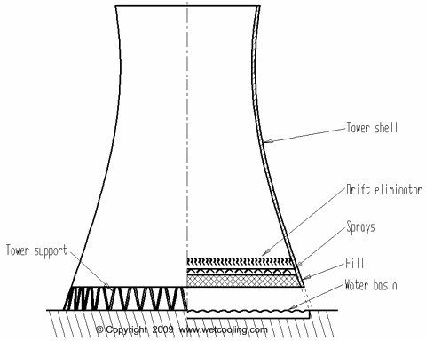
1. Natural Draft ( Hyperbolic CT ) :

  • ADVANTAGES : No fans, motors or gearboxes required, usually used for large quantity of water flow.
  • DISADVANTAGE : Large space required
  • uses the difference between ambient air temperature and the air inside tower.
  • Hot air rises upwards and cooler air is drawn inside through bottom.
  • Two types :
A) Cross flow Natural Draft CT: water and air flow are perpendicular. Fill is located outside CT.

Crossflow Natural Draft CT


B) Counter Flow Natural Draft CT: Air is dawn up through the falling water. Fill is located inside.


Counterflow Natural Draft CT


Friday, July 15, 2011

Centrifugal Pump


Centrifugal Pump

Fluid flows in axially and leaves radially outward i.e. in centrifugal direction , hence the name Centrifugal pump

At the eye of impeller partial vacuum is created and due to atmospheric pressure at the suction side, pressure difference is created due to which fluid flows.

  • Fluid enters pump (suction side) ---> rotating impeller pushes the liquid increasing velocity ---> liquid is discharged (discharging side) .
  • Mechanical Energy (motor) ---> Kinetic Energy (fluid) --> Potential Energy

( The impeller provides more Kinetic energy to the fluid. This Kinetic energy decreases as it moves up giving rise to Potential energy (head). KE decreases due to pump casing which slows down the
fluid due to resistance. )


HEAD : The maximum height straight up, the fluid can travel. It is a function of outer dia. of Impeller & motor speed.


centrifugal pump

Pump Head + Suction Head = Discharge Head .

Typical properties of centrifugal pump : ( reason why it is widely used )
  • constant head

  • varying flow

  • can handle huge amount of fluid at a time

  • suitable for LOW viscous fluids.

  • high speed flow.

Share it !!!