Sunday, November 04, 2012

NPSH


NPSH:


Net positive suction head measures the difference in head (differential head) & not the difference in pressure.


NPSHA
NPSHR
Absolute Pressure required at the pump suction above the vapor pressure of the liquid at that temperature.
(Psuction > Pvap)
It is the minimum absolute pressure required at the pump suction to avoid vaporization.
(Psuction = Pvap)

It is the function / requirement of your actual process / system
It is pump specific.
Hence it is calculated with the help of process parameters & conditions.
It is provided by pump manufacturer. It is calculated using water at room temperature by the manufacturer.


It is worth noting that while NPSHa must be greater than NPSHr, NPSHr test values stem from a procedure defined by Hydraulic Institute.
When the NPSHr value is determined by the pump manufacturer using water, the pump performance has already decreased by 3% in order to measure the change & so, NPSHa must actually be atleast a few feet/meter greater than NPSHr, not just equal.

READ MORE...

Friday, August 31, 2012

Pumps - Affinity Laws


Affinity laws allows engineers to estimate changes in critical performance parameters like

  • Flow rate (Q)
  • Head (H)** / Pressure (P)
  • Brake horsepower (BHP)
due to variation in
  1. Shaft / motor speed (N)
  2. Impeller diameter (D)
** Head refers to Total dynamic head (static head + losses OR differential head), since static head (process requirement) does not change with either shaft speed or impeller diameter or with flow rate.

Affinity laws are applicable on centrifugal pumps, fans or turbines (these are applicable only for centrifugal pumps, laws for fans are different) assuming the points on the system curve have approximately the same efficiency. The system curve changes with change in either shaft/motor speed or impeller diameter.

The following affinity laws are for a specific centrifugal pump.

Affinity law set 1
Affinity law set 2
Constant impeller diameter (d)
Constant motor speed (N)
Q α N
Q α D
H α N2
H α D2
BHP α N3
BHP α D3

Usually, there is no appreciable change in efficiency with range of normal operating speeds. Hence Affinity law set 1 can be considered accurate & reliable.

Whereas, on the other hand set 2 laws (same casing size, but different impeller diameter) are not as accurate as set 1 because large diameter reductions involve changes in the geometry of the blades (outlet width, blade angle, blade length) thus increasing the mismatch with the casing volute, which in turn causes change in the efficiency.

Note: The new impeller diameter should not be more than 10-20% of the original diameter.

The following affinity laws are for a geometrically similar pumps (meaning the pumps will run with same specific speed but with different impeller size.)

For set of geometrically similar pumps
Q α ND3
H α N2D2
BHP α N3D5

Tuesday, May 08, 2012

Absorption

ABSORPTION

Falling Liquid solvent absorbs the gas in the absorption column & is then sent into any one of he following unit:- Distillation, stripping section, removal through precipitation & settling, neutralization, oxidation, reduction & hydrolysis.


Purpose: 
  • Gas purification
  • Gas separation
  • Product recovery
  • Solvent recovery
Solvent Properties:
  • Solubility of gas should be high in selected solvent. ( If not, then absorption is a waste!! )
  • Low volatility organic liquid ( but water is preferred in many cases, due to easy availability & removal of water soluble gases like, HF, HCl, SiF4 ).
  • Low vapor pressure ( to reduce evaporative loss of solvent )
  • non-toxic, non-flammable, non- corrosive 
  • Low viscosity
Types of columns:


    Packed Column

  • Smaller column diameter application.
  • Large inter facial area for mass transfer
  • Simple and cheap in construction
  • Preferred for corrosive gases because of availability of ceramic / plastic MOC packing
Material & types of packing


Internals of Packed tower
  1. Packing support plate:                                                                                                                   It must bear the weight of the packings & allow unrestricted flow of down coming liquid. Drawback is that, that the packing blocks some holes, thus reducing the tower capacity. 
  2. Liquid distributor:                                                                                                                      Placed 6-12 inch above packing for allowing gas disengagement from the bed. Absorption & stripper columns require only one distributor, whereas, Distillation column requires 2 (feed & reflux)
  3. Liquid re-distributor:                                                                                                                        Some part of entering liquid flows through the wall without coming in contact with the gas flowing counter currently, thus we need a liquid re-distributor to collect the down coming liquid and distribute it uniformly throughout the bed and thus increase the efficiency of the tower.
  4. Demisters / Entrainment separators: Generally installed in exit gas streams for arresting the liquid droplets entrained in the gases. If demisters are not installed they can corrode / choke downstream equipments like heat exchangers tubes, damage tube sheets, contaminate products etc.
Types of packing :


Material of construction:
  1. Against all acid gases, metal tower, metal plates, metal packing or any other metal internals can have deleterious effect.
  2. Same is the case with organic liquid and plastic packing.
  3. Ensure internal cooling facility is available when materials and gases releases high heat of absorption.
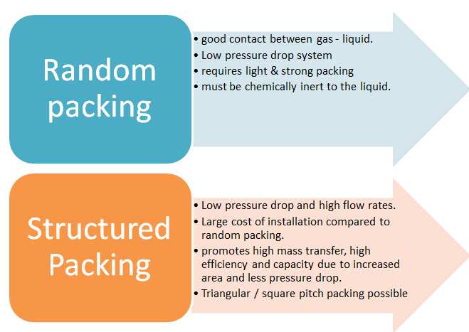
Dry & wet random packing:


Packed & plate column:


Monday, February 06, 2012

Dimensionless Numbers & their significance - 2 (Fluid Mechanics)


Significance:

  • Used in fluid flow calculations where local pressure drop is necessary (dp = upstream pressure - downstream pressure) 
  • Used to characterize the losses in the flow.
  • NEu = 1 corresponds to a perfect frictionless fluid flow.
=========================================================================


Significance:
  • It gives the possibility / potential of a fluid to cavitate.
  • If Ca < 0, Cavitation occurs & if Ca > 0 no cavitation will occur, since the condition to avoid cavitation is that the minimum pressure (Pmin)within the entire pump should be greater than the vapor pressure (Pv) of the fluid at that temperature. (Pmin > Pv )
=======================================================================


Significance:
  • It is the ratio of mean flow velocity to the speed of small gravity wave along the water surface.
  • It is an indication of resistance to partially submerged object moving through to water.
  • Greater Fr value, greater is the resistance to flow.
  • Fr < 1 indicates subcritical flow (tranquil flow)                                                  
  • Fr > 1 indicates supercritical flow (rapid flow)
  • Fr = 1 indicates critical flow.
  • Used in ship design i.e. to analyze water flow around ships.
  • Inverse of the square of Fr is called Richardson Number ( importance of natural convection to forced convection)
=======================================================================


Significance:
  • To check whether the fluid can be considered compressible or not.
  • If M < 0.2-0.3, then the fluid medium can be considered steady & isothermal & hence incompressible.
  • Used for fluids flowing with high speeds in channels, nozzles, diffusers etc.  
  • It is analogous to Froude Number
C = speed of sound = 345m/s (at 15 deg. celsius temperature)


========================================================================


Significance:
  • It is the square of mach number (Mach number can also be expressed in terms of bulk modulus as the square root of cauchy number number).
  • Used to study compressible flow.
K = bulk modulus of elasticity

========================================================================


Significance:
  • Used to study fluid friction in pipes.
Tw = wall stress
ef = friction loss

=========================================================================


Thursday, December 22, 2011

Dimensionless Numbers & their Significance


Nomenclature:


D = diameter of pipe
DH = Hydraulic diameter
L = Length of the pipe
Lch = characteristic length
R = Length through which conduction occurs.
u = mean characteristic velocity of the object relative to the fluid.
Vch = Characteristic velocity
Cp = specific heat capacity at constant pressure.
k = thermal conductivity
μ = dynamic viscosity of the fluid
{\rho}\, = density of fluid.
DAB = mass diffusivity
h = heat transfer coefficient.
g = acceleration due to earths gravity.
t = characteristic time
ν = Kinematic viscosity of fluid.
α = Thermal diffusivity
β = volumetric thermal expansion coefficient ( = 1/T for ideal fluids, T = absolute temperature)
Ts = surface temperature
T∞ = Bulk Temperature


Significance:

  • Ratio of Inertial forces to viscous forces.
  • Primarily used to analyse different flow regimes namely Laminar, Turbulent, or both.
  • When Viscous forces are dominant its a laminar flow & when Inertial forces are dominant it is a Turbulent flow.
=======X=======X=======X=======X=======X======X=======X=======X====


Significance:
  • Depends only on fluid & its properties. It is also ratio of velocity boundary layer to thermal boundary layer
  • Pr = small, implies that rate of thermal diffusion (heat) is more than the rate of momentum diffusion (velocity). 
  • Also the thickness of thermal boundary layer is much larger than the velocity boundary layer.
=======X=======X=======X=======X=======X======X=======X=======X====


Significance:
  • Analogous of Prandtl number in Heat Transfer.
  • Used in fluid flows in which there is simultaneous momentum & mass diffusion
  • It is also ratio of fluid boundary layer to mass transfer boundary layer thickness.
  • To find mass transfer coefficient using Sherwood number, we need Schmidt number. 
=======X=======X=======X=======X=======X======X=======X=======X====


Friday, September 02, 2011

Heat Exchanger - 3

Fouling in Heat Exchanger 
-----------------------------------------------------------------------------------------------------------
General :


  • Deposition of extraneous material on Heat transfer (HT) area.
  • Resistance to flow
  • increases Pressure drop in order to maintain the flow rate.
  • Must be considered during designing & ease of cleaning must be permitted.
  • More fouling fluid allocated to tube side & allow access for cleaning
  • keep fluid velocity constant
  • 5 ft/s for tube side & 3 ft/s for shell side for fouling fluid


Fouling Types:


Fig. 1. Types of Fouling
fig. 2. Corrosion Fouling

fig. 3. Chemical Fouling
                    

fig. 4. Crystallization Fouling

fig. 5. Biological Fouling


Tuesday, August 30, 2011

Heat Exchanger - 2

LMTD & Correction Factor (F)
-----------------------------------------------------------------------------------------------------


---------------------------------------------------- (1)
Q = Heat transferred in H-E-X
U = Overall Heat transfer coefficient
F = Correction Factor.
 = Logarithmic Mean Temperature Difference (LMTD)
* LMTD is dependent only on inlet and outlet temperatures and is independent of type of HE used.

where, 

1-stands for Inlet                                                  
2-Stands for Outlet

  • Normal Practice if to calculate LMTD for counter flow and apply correction factor F to it.


Fig.1. LMTD for single pass STHE

Fig.2. LMTD for 1/2 STHE
F (Correction Factor)
  • Shows departure form true counter current flow
  • F is correction factor for multi-pass and crossflow heat exchanger and given for two-pass shell-and-tube heat exchangers in equation (4) below.
  • 0 < F < 1
  • fn { fluid Temperature, no. of passes }
  • F > 0.8, if not then redesign the HEX with more no. of passes or larger LMTD
Find F value:
  1. Find R using:

------------------------- (2)


     2. Find P using:

Sunday, August 28, 2011

Heat Exchanger - 1


Heat Exchanger – Classification


Applications :

  • Air Conditioners
  • Refrigeration
  • Natural gas processing
  • Petrochemical Plants
  • Power Plants
  • Radiators (cars, bikes, IC Engines and so on.)
  • 99% of Chemical plants
Types :

  • Basic Classification:


Recuperative:

  • Fluid flows in separate conduits
  • Heat transfer from hot fluid to cold fluid across the walls

Plate H-E-X
  • Plate & Frame


Fig. 1 .Plate & Frame H-E-X

  1. Series of rectangular parallel plates
  2. Held firmly with each other.
  3. Sealed by gaskets.
  4. Hot fluid passes through alternate pairs of plates transferring heat to cold fluid in adjacent spaces.
  5. Cleaning easy

Share it !!!